Smart Footwear Sensor
A smart work boot with embedded pressure sensor to prevent unnecessary amputations
The Smart Footwear Sensor is an ongoing hardware and software project that aims to embed high resolution pressure sensing into a pair a shoes that can be worn for long periods of time. The project’s goal is to reduce the likelihood of serious foot injury brought on by diabetes. Some of these injuries can result in partial or complete amputation of the foot. By making making patients aware of what is happening in their shoes we hope to prevent these injuries before they get to that serious stage. Currently most pressure logging systems only measure a couple of steps, being worn only for a few minutes. By logging long term data the hope is that the sensor will be able to notice changes in day to day pressure patterns and inform the wearer before lasting damage occurs.
The project is a collaboration between Computer Science, Design and Medicine at Monash University and external partner Blundstone, a Tasmania based manufacturer of work boots.
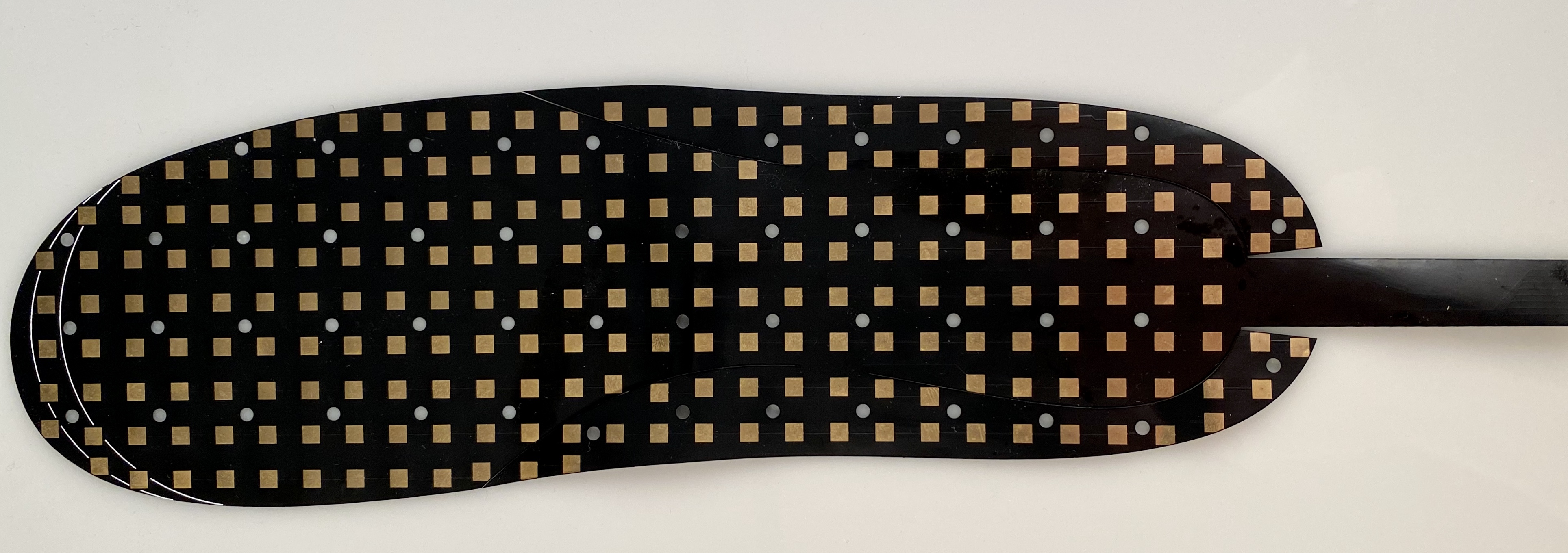
My role has been the hardware design and firmware programming. There have been a number of hardware challenges to overcome. The first was what kind of sensing technology should be used. After evaluating a few possibilities the best performer was a resistive sensor. A flexible pressure sensor can be created using a conductive plastic film. This film varies it’s electrical resistance based on compression, if you place two electrodes on the film you can measure this change in resistance. I realised that I could make a set of flexible circuit boards and sandwich the plastic film between them. The flexible circuit boards would have a number of contact points on them that would attach directly to the plastic. One side of the sensor would be arranged as rows of sensor points, the other side would be columns. By switching on one row and one column the sensor is able to read a specific point on the sole.
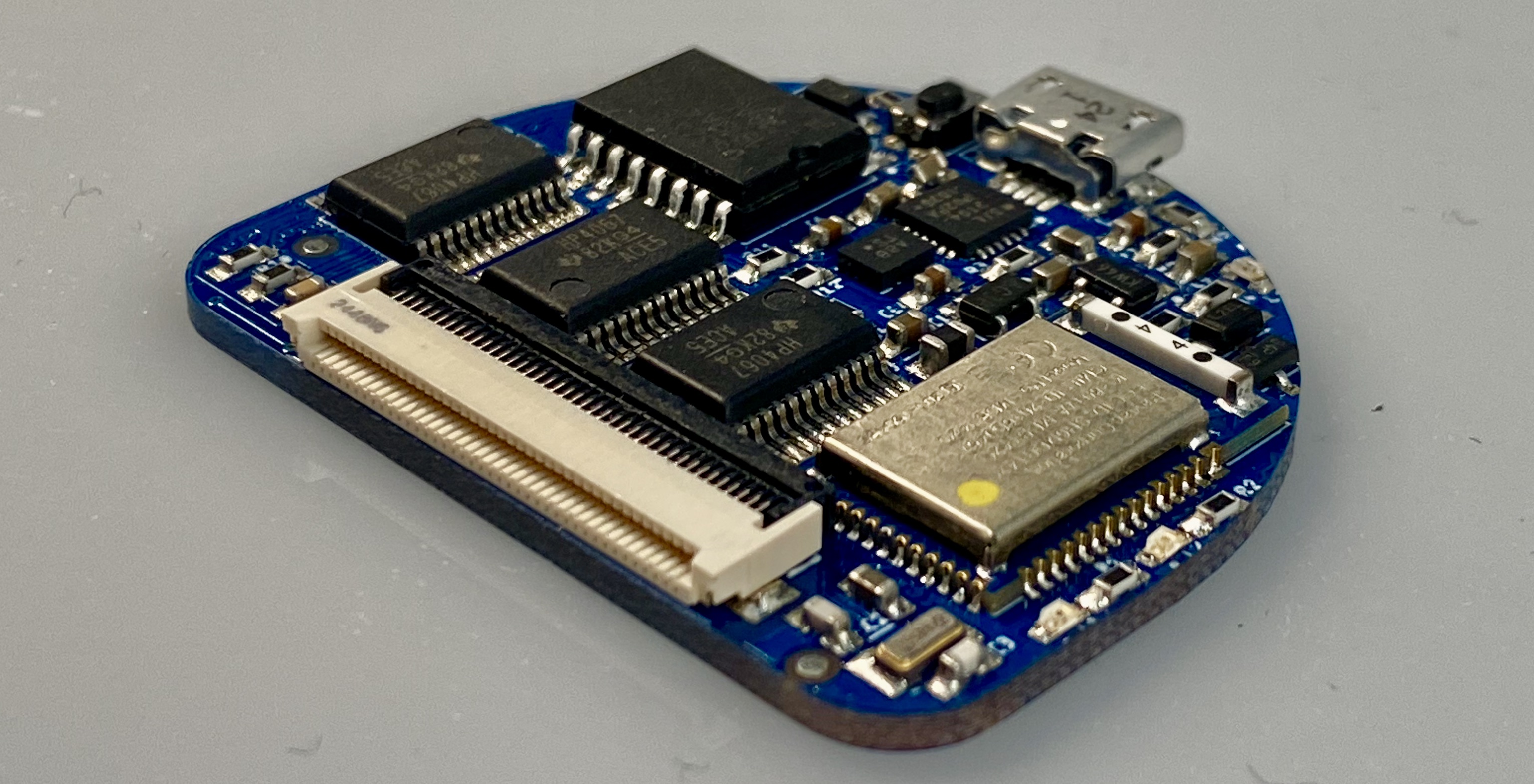
After the sensor technology was determined the next step was to create a control board that can read the sensor, log the data and report back to the user. The reading of the sensor is achieved by 3 multiplexers that are connected to the sensor via a 40 pin flex PCB connector. This connector can be reversed allowing the same circuit boards to be used for both left and right soles. The multiplexers are able to quickly switch on a specific row and column so the microcontroller can make a reading. The board is capable of reading and logging all 220 sensors at a rate of 20 times a second. The data logging is achieved through a Real Time Clock that ensures the data is correctly timestamped and a MicroSD card which is inserted on the bottom side of the board. Control of the sensor and download of the logged data is achieve via Bluetooth. The microcontroller that powers the board contains a full Bluetooth LE stack allowing for wireless communication with external devices. The control board also includes a 6 axis Inertial Measurement Unit (IMU) to log the overall rotation and movement of the foot.
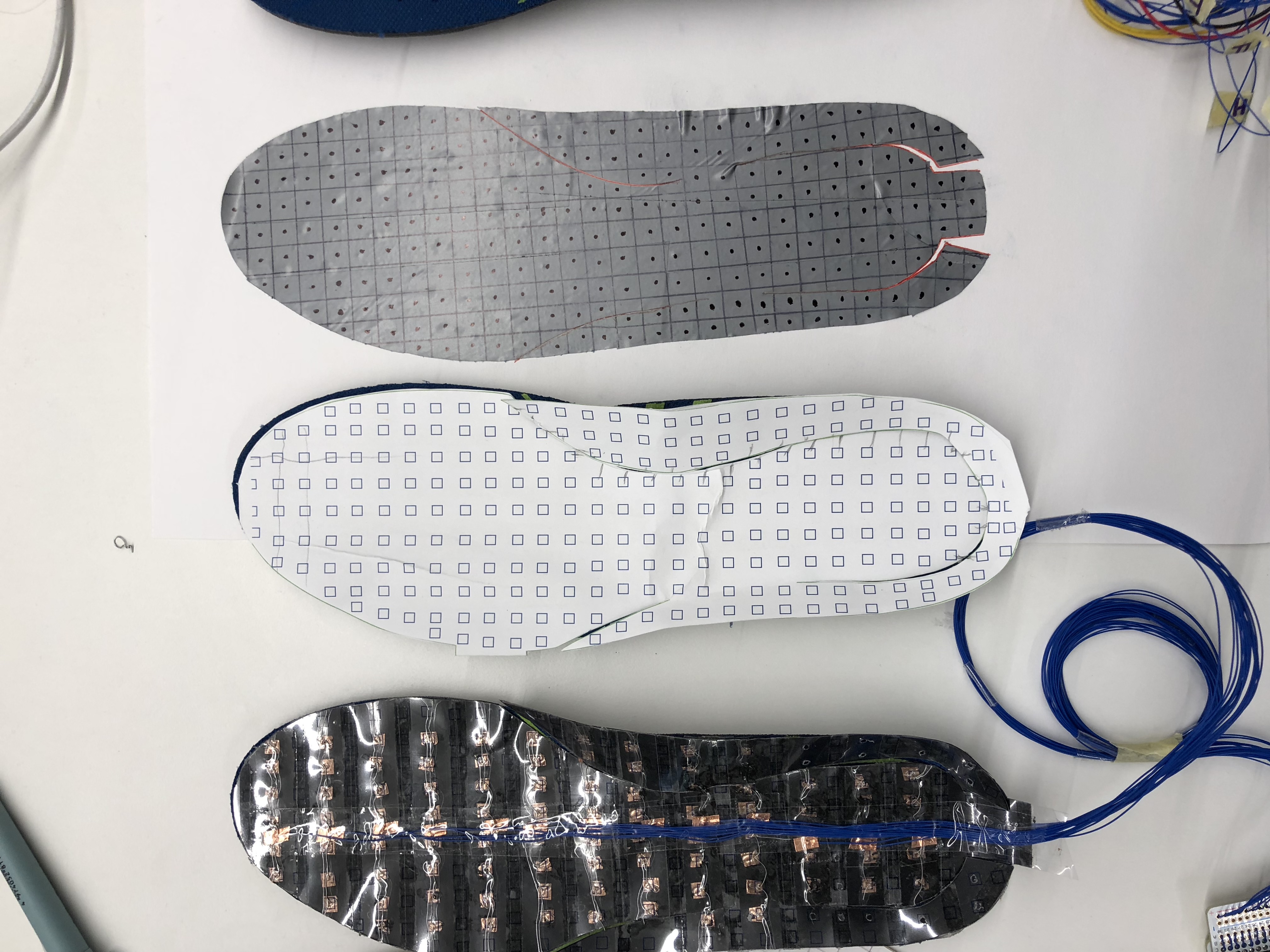
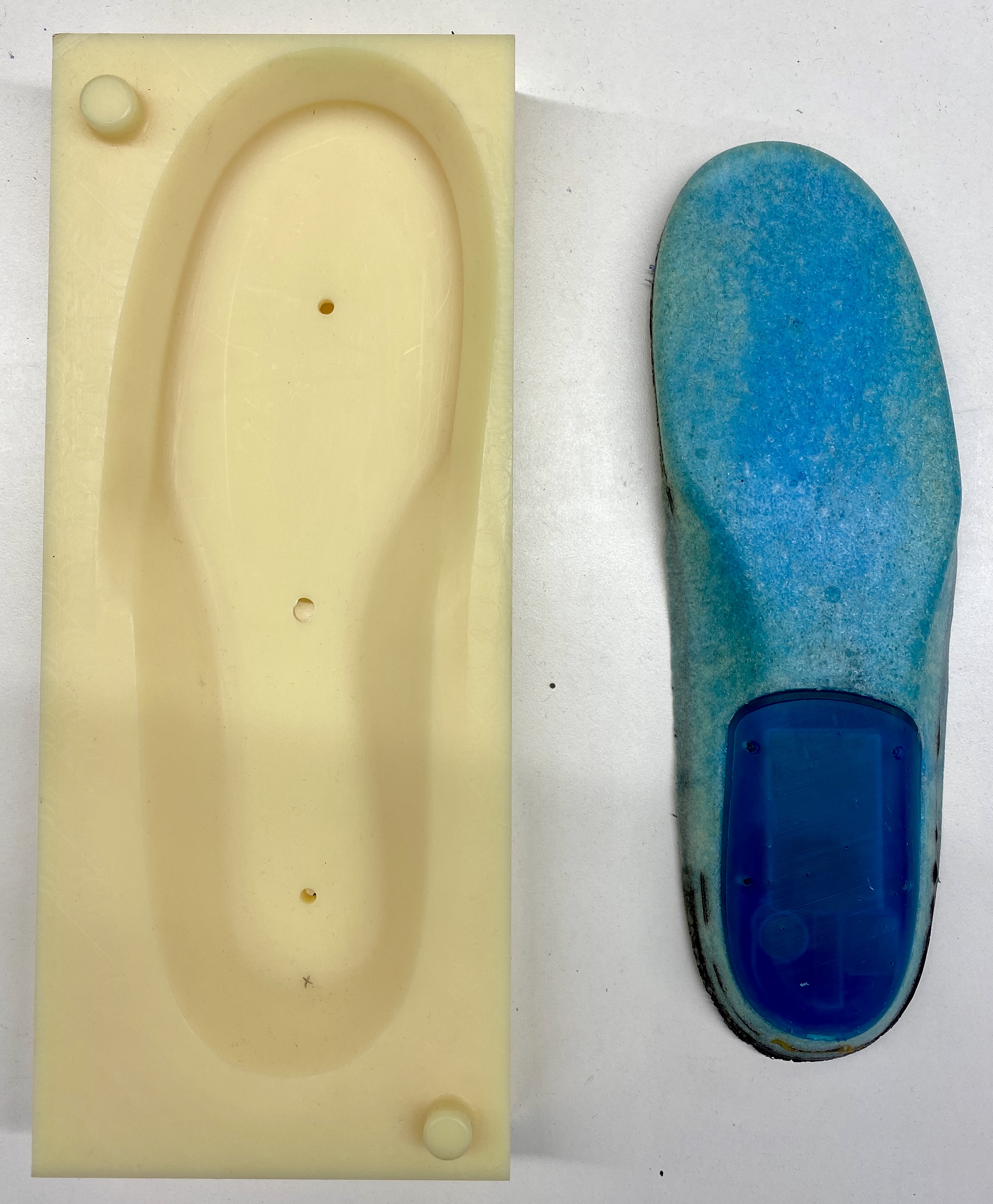
Next step was to work out how to embed everything into the in-sole of a shoe. Initially we tried casting our own in-soles. We made moulds and used a two step casting process with polyurethane foam embedding the flexible sensor in between two bonded layers of foam. While this approach was successful a few times, it was difficult to keep consistent with the setup we had on hand. The sensor in the final prototype ended up being bonded to an existing off-the-self in-sole in order to remove this inconsistency.
The placement of rigid components (i.e the circuit board, battery and charging coil) also proved to be a challenge. Initially I tried placing the components in a rigid enclosure that formed part of the in-sole. This was mainly to see if we could keep the whole device as an in-sole so that it could be placed into a number of different shoes. However after wearing the shoes for only a few hours the hard enclosure made them extremely uncomfortable.
We reached out to Blundstone and asked them if it was possible to have a pair of shoes made with a cavity in the heel. This would allow us to place the rigid elements of the sensor below the level of the in-sole and hopefully remove the discomfort from having little padding between the foot and enclosure. They were able to get a pair of boots made for us and I was able to move all of the rigid components into a small holder that can sit in the heel of the shoe.
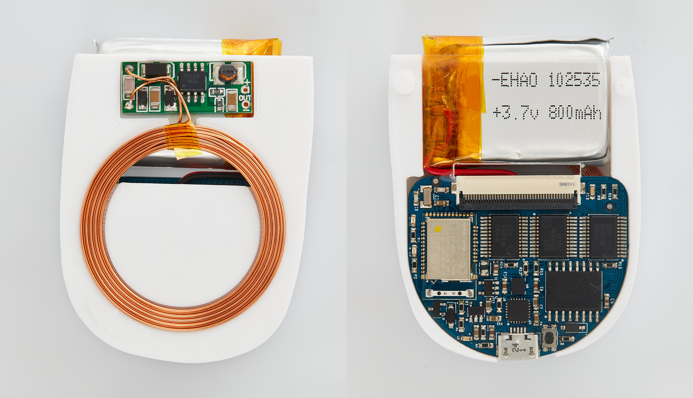
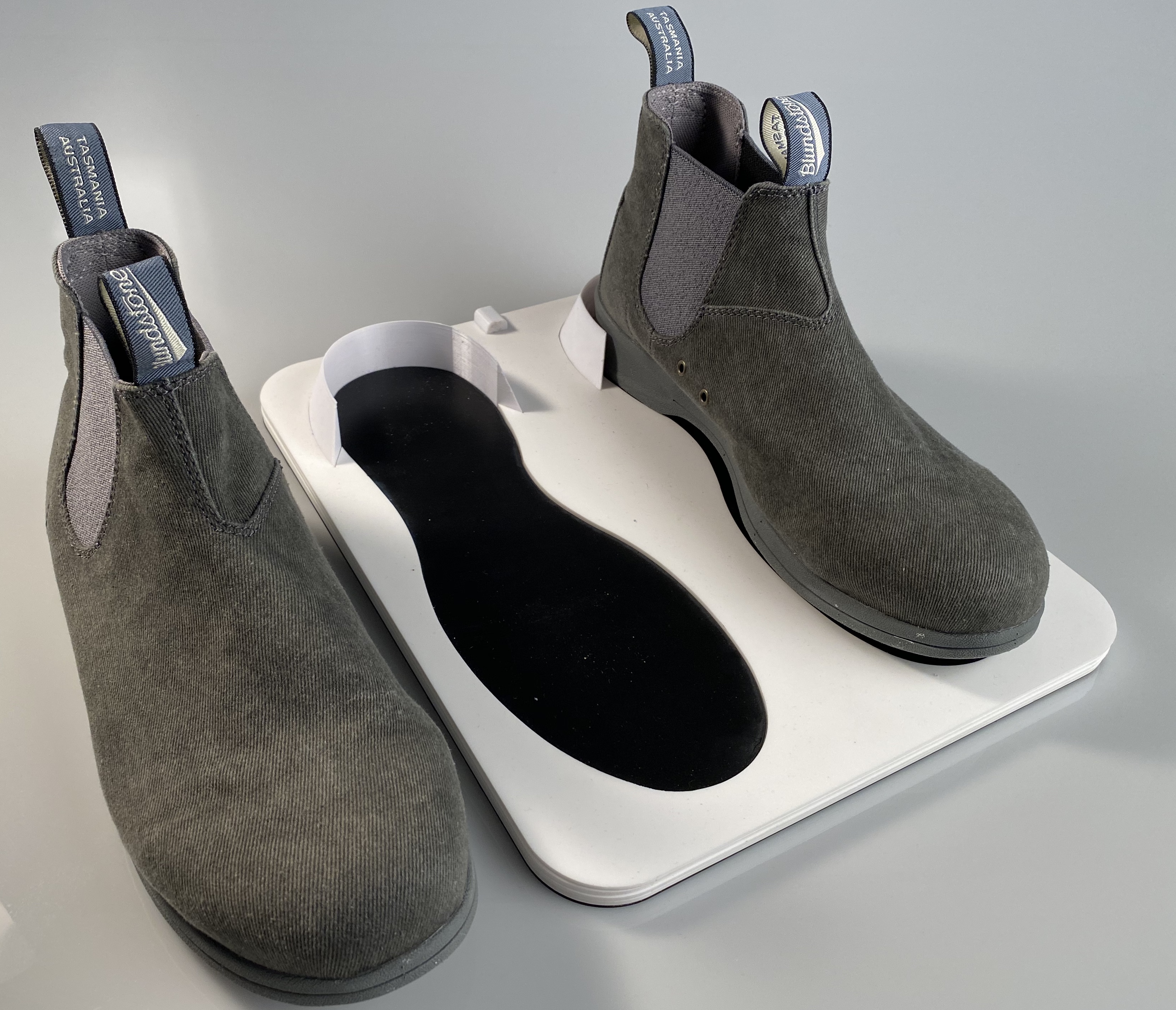
I was now able to fit all of the components and sensors into the boots, the final challenge was ensuring the battery could be recharged. This was solved through the use of wireless charging. I designed a simple charging mat that the boots can be placed on at the end of the day to ensure they have a full charge for the next day. The final pair of boots were indistinguishable from a normal pair of boots.
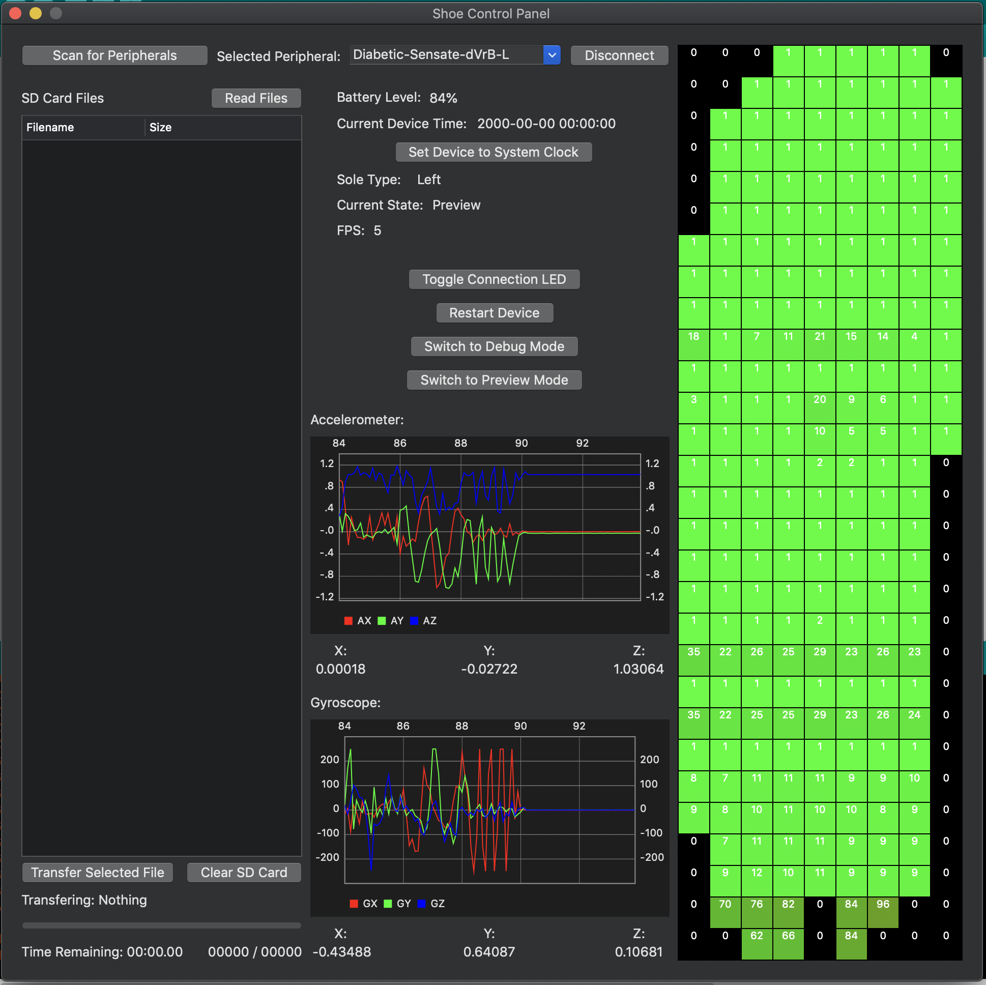
The last step to ensure that the prototypes were a complete system was a simple ‘control panel’ app that allows the user to control the sensors and to download the logged data. This app took the form of a native macOS app developed in Xcode due to the ease of BLE development on that platform.
